He developed the advanced power electronics concept for civil aircraft power system, high temperature power semiconductor and aircraft power conditioning and actuation systems. He has developed a number of electric vehicle techniques including the battery charging system, battery management, electric drive, lighting, power conversion, in-wheel and integrated charger.
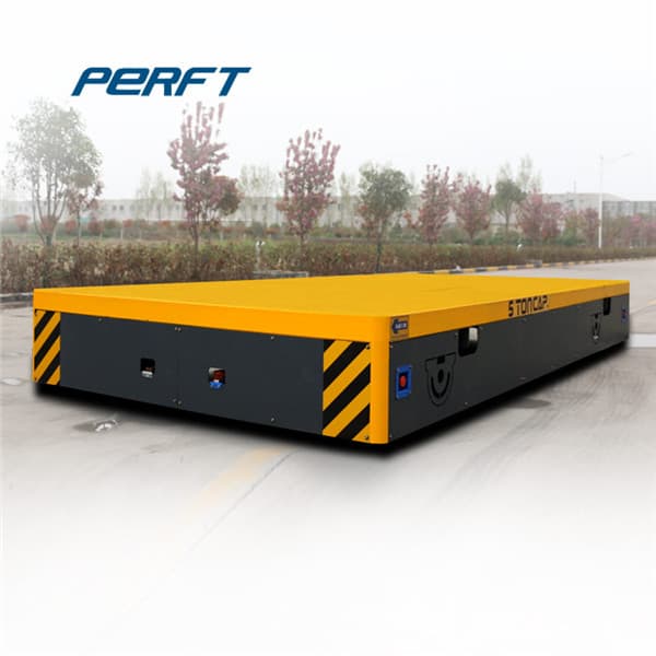
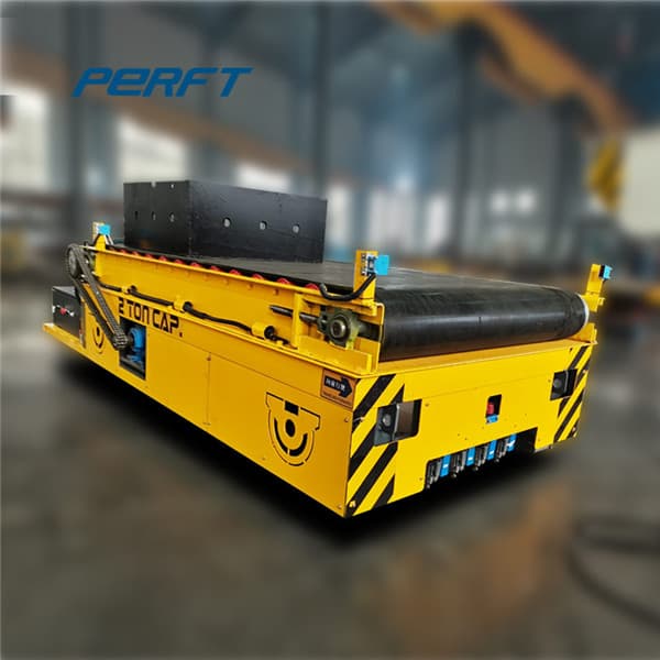
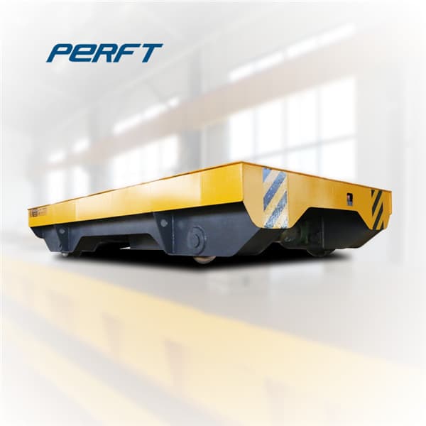
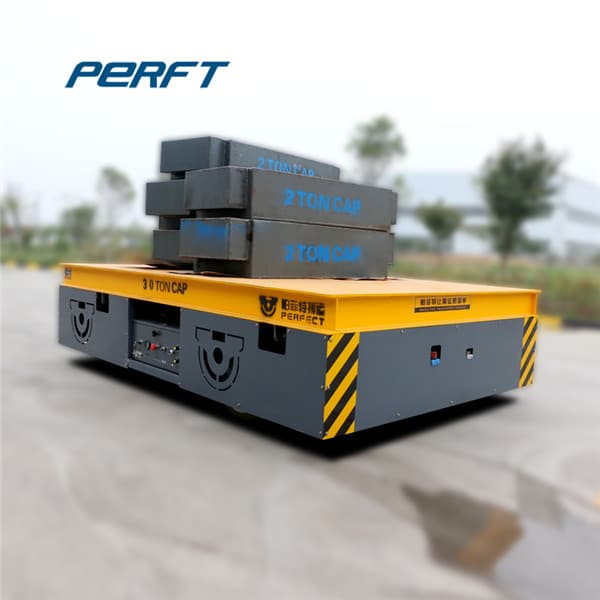
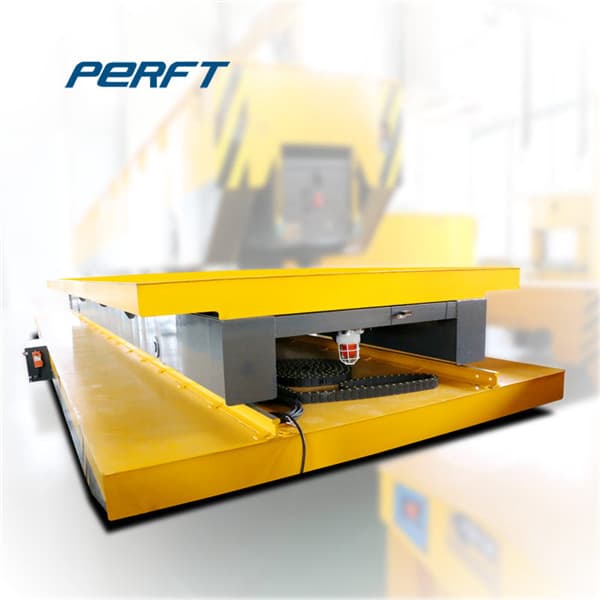
Transfer cars are manufactured with sufficient ground clearance. For travel length above 6 meters, optional features of Cable reel drum is provided for protection and longer life of cables. Optional features like rotating light, warning alarm, sling box and oil collection trey can be provided as per the customer’s need. 20MT billet transfer car.

The YELLOWTOP® high-performance AGM battery is one of the few true dual-purpose automotive batteries available. With premium cranking power and impressive cycling capability, this heavy-duty battery is also perfect for modern accessory-loaded vehicles. Low internal resistance also provides more consistent power output and faster recharges.

Significant research has been pursued over last two decades in the development of efficient EV charging methods. A preliminary review of few methods developed for wireless charging revealed that ICPT is a promising and convenient method for the wireless charging of EVs. This paper includes the equivalent circuit analysis and characteristics of
The transfer of power from source to receiver is a technology that has existed for over a century. Wireless power transfer (WPT) has been made feasible in recent years due to advances in technology and better The MPT system works by converting power to

power transfer efficiency, wireless charging is a winning combination. Electric Vehicles set for growth the use and acceptance of electric vehicles (evs) amongst businesses and consumers will become more prevalent, driven by investment from the automotive
1/10/2018 · Wireless power transfer system with an asymmetric four-coil resonator for electric vehicle battery chargers IEEE Trans. Power Electron. , 31 ( 2016 ) , pp. 6844 -
31/3/2016 · Of course, gasoline doesn't exist in a vacuum, either: Refining, processing, and transporting gas add emissions that car owners must factor into their overall carbon footprint, the so-called "well

Irwin Car offers a wide range of custom-designed locomotives and personnel carriers, as well as transfer and utility vehicles that are ideal for mining, tunneling and above-ground industrial use. Our locomotives are powered by diesel, battery, trolley and a combination of battery/trolley, while our transfer cars can be AC, DC, battery, diesel

Wireless power transfer. Inductive charging pad for a smartphone as an example of near-field wireless transfer. When the phone is set on the pad, a coil in the pad creates a magnetic field which induces a current in another coil, in the phone, charging its battery. Wireless power transfer ( WPT ), wireless power transmission, wireless energy

With load capacities that range from 5 Ton to 300 Ton, our Industrial Transfer Cars are equipped with single and double flange steel wheels, in 12" to 30" diameters. Our wheels are machined to "press-fit" tolerances mounted on either stub or thru axles. Each axle assembly is mounted to the frame of the vehicle using pillow block or "AP" bearing

IEEE ICSET 2012, Nepal Design of Static Wireless Charging Coils for Integration into Electric Vehicle Subhadeep Bhattacharya, Student Member, IEEE, and *Y.K.Tan, Member, IEEE Energy Research

12/6/2018 · See more information: http://www.bfbtransporter.com/ Contact us if you have any needHenan Perfect Handling Equipment Co.,Ltd. Tel: 0086-373-3020116 F

30/7/2021 · The electromagnetic induction method of wireless power transfer uses a system which consists of an amplifier unit, power transmission coil, power reception coil, and power reception unit. The power transmission coil unit and power reception coil unit are similar to a structure in which the transformer core is divided to create an empty space, or "air gap".

Magnet moving through copper coil Figure 3-1: Diagram of proposed rotor design The system for the rotor powered battery charger must be placed in an area in the car to keep it from breaking and yet in a place close enough to the rotor for the circuit to work12 I
